I own a little Behringer Xenyx 802 mixer. It’s a nice and useful unit but it’s most annoying feature is the post-fader aux (FX) channel. Post-fader means that the audio signal level sent to the AUX send output depends on the level of the main channel fader. If you need the AUX (FX) channel to be totally independent you need to make it pre-fader. Pro mixers that come with multiple AUX buses may have some of them pre, some post and others switchable. The post-fader bus is usable when connected to effect loop. Effect level will depend on the channel level setting. Pre-fadeed AUXes are used for monitoring and other audio routing (recording mix may be different that FOH mix for example).
My case is a little different but also requires pre-fader AUX.
As a drummer, I also control the playback of pre-recorded stuff. At the same time I need a click. In the rehearsal or small gig setup I use condenser microphone to better hear the “room” and in the concert I grab the monitor signal over the DI Box. Therefore I have up to 4 tracks that need to be mixed into my monitor signal. In addition to that the playback signal (one channel) has to be sent to FOH or practive room PA system. This is where pre-fader AUX comes in handy.
I decided to do that for two stereo channels and left the mono channels unmodified. You can easily find corresponding connections for the mono channels. Doing it for the stereo channels my be also useful for DJ’ing and monitoring deck signals over AUX send output. This would in addition require using a stereo to mono headphones adapter.
The mod is pretty simple. As there is no schematics I used trial and error method and the multimeter to locate signals on the board. All you need is to solder in a summing resistor (I used 680R but I think 750R would be more accurate) between the direct pre-amplified signal signal and the input pin of the AUX pot. I don’t think this is the best way to do it but it works so I don’t really care.
Locate the R120 and R119 surface mounted resistors and solder the summing 750R resistor as pictured, to the middle pin of the potentiometer (three vertical pins between the R120/R119 resistors and the IC13/IC12) and the “bottom” pad pod the R120/R119 resistor.
Don’t overheat the SMD resistor pads as they can burn and lose contact. If you don’t know how to solder better practice first.
I’m not responsible for any damage of the equipment nor soldering burns and electric shocks you could receive while following this manual. Have fun.
Should you have any questions email me : chris [at)] koston.us
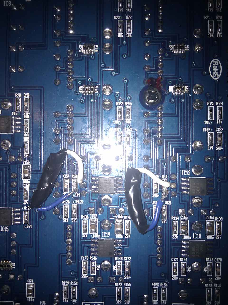
802 mod picture